1. Introduction
Rocks inherently contain numerous cracks and joints throughout their formation process. And intricate natural phenomena, including weathering, crustal movements, and chemical erosion, further intensify these imperfections. These deficiencies render rock masses more prone to failure, thereby posing considerable safety risks to human settlements and engineering endeavors [,,]. For instance, a landslide disaster in Yunnan Province, China, in January 2024, buried houses and resulted in the tragic loss of 44 lives []. The Chengdu-Kunming Railway encountered a special geohazard characterized by coexisting large deformations and rock bursts during construction in Panzhihua City, Sichuan Province [], fortunately without causing casualties. In December 2022, a fatal rockfall event occurred in Yosemite National Park, California, USA, leading to two deaths []. Regardless of whether in engineering or natural environments, studying the impact of cracks on rock masses and preventing natural disasters is of great significance [,], providing greater protection for people's lives and property safety.
To better understand the development of rock cracks and their influence to rock masses, scholars have derived mechanical models of crack-induced rock failure and the effects of various factors through theoretical research. Zhu et al. [] established the stress-strain constitutive relationship for complex rock masses by considering the rock as sponge material. Bahmani et al. [] developed a random damage model for rock fracture based on the Mohr-Coulomb failure criterion and effective stress relationships, which can capture the rate sensitivity of the strain-stress response. Wu et al. [] developed a cohesive fracture model to study the effects of rock heterogeneity on its dynamic failure process and dynamic strength. Wei et al. [] created a brittle fracture model to predict the tensile mode-I failure load of cracked rocks, which has great potential for analyzing the size effect of apparent fracture toughness. Cui et al. [] proposed a new numerical procedure for the implementation of VCSM on the basis of Hoek-Brown failure criterion and the non-associated flow rule, investigating the variation of the stress components, strain-softening parameter, and strength parameters in the plastic softening zone. The development of theoretical models has provided significant inspiration for research. However, due to the complexity and uncertainty of influencing variables in reality, they are only suitable for simple models.
Experimental research stands as the most direct avenue for acquiring macroscopic mechanical properties of fractured rock masses. By conducting loading experiments on these masses, we can attain not only the stress-strain characteristics of the rock, but also gain insight into the propagation and development patterns of cracks. Numerous researchers have conducted experimental studies to investigate these propagation laws. For instance, Wang et al. [] carried out drop-weight tests on four sets of sandstone with parallel cracks at different dip angles under dynamic loads, exploring the dynamic response mechanisms of sandstone with saturated, ice-filled parallel cracks. Li et al. [] performed three-point bending (TPB) experiments on granite samples of varying amplitudes subjected to pre-peak constant amplitude cyclic loading (PPCACL), finding that with increasing PPCACL amplitude, the fracture energy, tensile strength, fracture toughness, and monotone loading peak of granite samples all decreased. Yang et al. [] utilized the SHPB impact test system, considering the effects of stress and strain rate, to conduct dynamic mechanical characteristic studies on anchor-strengthened single fractured red sandstone samples under different surrounding pressures and impact speeds. Yan et al. [] conducted both laboratory experiments and numerical simulation analysis to investigate the dynamic fracturing of roughly jointed granite under various loading rates, finding that the surface roughness has a significant effect on dominating dynamic fracturing behaviors of jointed rock and loading rate affects the dynamic response and fracture patterns of these jointed rocks. Liu et al. [] studied the mechanical properties of fractured rock masses in cold-region slopes, conducting freeze-thaw cycle tests and uniaxial compression tests on prefabricated fractured blue sandstone with different dip angles and widths, finding that freeze-thaw cycles significantly affected the stress-strain curves of this type of rock. Wang et al. [] examined the influence of surrounding pressure and fracture dip angle on the mechanical behavior of granite surrounding rocks, taking intact granite and granite with single fractures of different dip angles as research subjects and conducting uniaxial and triaxial compression tests. Luo et al. [] conducted a series of triaxial hydraulic coupling tests on sandstone with prefabricated fractures at different dip angles, studying strength and deformation characteristics, macroscopic failure modes, and permeability of prefabricated fractured sandstone samples affected by the dip angle of the prefabricated fractures. Zhao et al. [] employed acoustic emission and digital image correlation techniques to study crack propagation and fracture patterns in Brazilian splitting tests, using 3D scanning technology and fractal theory to analyze the influence of fracture patterns on the surface morphology of fracture surfaces. Zhao et al. [] conducted uniaxial compression tests on rock masses with different fracture dip angles, using digital speckle and acoustic emission methods for observation to explore the fracture evolution process of rock masses with varying fracture dip angles, analyzing the evolution rules of surface and internal fractures in different single fractured rock masses. Zhu et al. [] selected single fracture samples with six different fracture dip angles and similar three-dimensional fractal dimensions for seepage tests, demonstrating that fluid flow and strain in fractured rock masses are jointly affected by fracture dip angle and underground depth stress state, with the degree of influence of fracture dip angle changing with increasing underground depth. Zhang et al. [] conducted Brazilian splitting tests on sandstone with three types of fractures: single fracture, collinear double fractures, and parallel double fractures, analyzing the fracture patterns at different fracture dip angles and classifying them, while also examining changes in tensile strength of the three types of fractures at different dip angles. Yun et al. [] prepared parallel double fracture quasi-sandstone samples with varying dip angles, conducting triaxial compression tests after a single freeze-thaw cycle to analyze the development of pores, crack propagation, damage evolution, and failure characteristics. Fan et al. [] utilized the SHPB test system for experiments, employing a high-speed camera system to record the destruction process of samples, obtaining stress-strain curves and destruction characteristics under dynamic loads, and analyzing the effects of crack angles and impact pressure on the mechanical properties of double fractured sandstone. Wang et al. [] employed the MTS816 rock servo test machine for uniaxial compression tests, in conjunction with the particle flow program to study the mechanical properties, crack evolution rules, and destruction characteristics of multi-fractured coal bodies with different fracture positions. Yuan et al. [] conducted four sets of true triaxial rock burst tests to determine infrared precursors of rock bursts in sandstone with different bedding dip angles, analyzing rock burst characteristics from stress-strain curves, rock destruction modes, average infrared temperature differences (AITD), average infrared standard deviations (AISD), and corresponding spectral analyses.
Numerical simulation, as the "third method" of scientific research, not only verifies the correctness of theories and experimental studies but also reflects the intrinsic mechanical mechanisms of deformation and failure in fractured rock masses. As long as reasonable constitutive models and mechanical parameters are given, numerical simulation can provide accurate answers, making it favored by many scholars since its inception. Ma et al. [] used 3 DEC numerical simulation experiments to simulate the evolution law of mined covered rock stress. Ma et al. [] conducted uniaxial compression tests and numerical simulations on model samples containing tunnels and cracks, studying the influence of the inclination angle of the main crack, the distance between the crack end and the hole wall, the length of the crack, and the angles of primary and secondary cracks on the compressive strength of the model. Based on similar simulation and numerical methods, Huang et al. [] studied the evolution of mining fractures in coal seam groups and the influence of faults on their evolution. An et al. [] implemented a fracture model in the HFDEM for simulation of the three main fracture types, concluding that the HFDEM can model the entire and complete rock fracture process during the three convention bending tests. Yan et al. [] developed a discrete element numerical model considering the influence of mineral crystal structure, conducting compression tests on fractured granite under different surrounding pressures. They established an empirical model for granite stress peaks under the influence of surrounding pressure and crack angles, clarifying the mechanism of granite microfracture rupture from the micro-scale.
PFC differs from other numerical simulation software by its exceptional capability to manage material discontinuities, including rock fractures, collapses, and particle flows, which are challenging to accurately simulate using continuum mechanics models. The software's edge is its capacity to offer profound insights into the microstructural and failure mechanisms of materials, coupled with its versatility and adaptability in replicating the behavior of intricate granular materials. These attributes render PFC an indispensable asset in the domains of rock mechanics and engineering. For example, Li et al. [] combined micro parameters calibrated by indoor experiments and used a two-dimensional discrete element particle flow program (PFC2D) to conduct numerical simulations on combined sample specimens, exploring the influence of different fracture dip angles on the strength and energy evolution of granite-concrete combined samples under uniaxial compression. Han et al. [] studied the influence of thin spray materials on the strength, deformation, and energy evolution characteristics of intact and fractured red sandstone under uniaxial compression conditions, using the particle flow PFC3D software to analyze the effects of thin spray materials on crack propagation characteristics in samples with different fracture dip angles. Chen et al. [] utilized uniaxial compression tests combined with DIC technology to study the effects of fracture dip angle and number on the mechanical properties, surface deformation field, and crack propagation paths of rock-like samples. Si et al. [], based on indoor uniaxial and triaxial compression tests, used discrete element software to construct a triaxial compression particle model of composite rock containing coplanar double fractures, systematically studying the mechanical behavior, energy, and micro-crack evolution laws of composite rocks under different fracture dip angles, lengths, and surrounding pressures. Ding et al. [] simulated the crack propagation process of rock-like materials with double prefabricated cracks under biaxial compression tests using three-dimensional discrete element software (PFC3D) and an improved parallel bonding model (IPBM) to explore the propagation and linkage mechanisms of defects (fractures) inside rocks under complex stress states. Qian et al. [] reproduced different types of cracks, including wing cracks, anti-wing cracks, shell-like cracks, and spalling fractures, through finite elements, analyzing the influence of different defect dip angles on the initiation and propagation of these cracks under dynamic loading conditions. Liang et al. [] simulated fractured rock masses through the discrete element simulation software PFC2D, discovering the main forms and causes of rock mass failure from a microscopic level by analyzing the distribution of rock particle force chains. Sun et al. [] used PFC2D to establish a numerical model of sandstone samples containing parallel double fractures with different spatial distributions, conducting uniaxial compression tests, analyzing damage characteristics, micro-crack evolution, and stress field distribution, and discussing the destabilization mechanisms of the samples in conjunction with macroscopic failure characteristics. Wang et al. [] used particle flow software PFC2D to obtain the micromechanical parameters of white sandstone and explored the effects of parallel double fractures on the mechanical properties, crack propagation, and energy evolution by varying two key influencing factors: double fracture dip angle and spacing. Dai et al. [] employed a two-dimensional particle flow program to simulate the separated Hopkinson bar one-dimensional impact test, comprehensively studying the initiation, propagation, and penetration processes of cracks in parallel double fracture samples. Hong et al. [] systematically studied the interaction between parallel double fractures through finite element methods, experimental research, and theoretical analysis, focusing on brittle and ductile materials. Zhou et al. [] investigated the strength, failure, and crack evolution of intersecting fractured rock samples under shear load through indoor experiments and numerical simulation, developing a Smoothed Particle Hydrodynamics (SPH) algorithm based on the virtual coupling method to simulate the fracture of V-shaped crack sandstone samples under direct shear.
This paper performs numerical simulations of crack propagation within Brazilian disk rock samples, featuring five distinct fracture dip angles (0°, 30°, 45°, 60°, and 90°) and five varying horizontal projection distances of double cracks (0 mm, -10 mm, 10 mm, 20 mm, and 30 mm). The simulation results are subsequently validated by comparing with experimental results, validating the accuracy of the simulation method. Furthermore, the study delves into the mechanical intricacies governing crack propagation in Brazilian disks, offering insights that contribute to a deeper comprehension of deterioration patterns in fractured rock masses.
2. PFC2D Simulation of Rock Crack Propagation Under Different Fractures
2.1. Numerical Model
The sample model is a Brazilian disk sample with a radius of 50 mm and a fracture length of 20 mm. The fracture was created using the fish language, and the particles in that area were removed. The PB model is used between particles, while the SJ model is employed for fractures. The simulation is conducted in two groups, each consisting of five samples, totaling 10 samples. The first group involves models with a single fracture at various dip angles: 0°, 30°, 45°, 60°, and 90°. The second group includes models with double fractures at different distances, with both fractures having a dip angle of 45°. The horizontal projection distances between the centers of the two fractures (taking the difference in horizontal projection between the lower and upper fractures as positive) are 0 mm, -10 mm, 10 mm, 20 mm, and 30 mm. The samples undergo uniaxial compression at a consistent loading rate of 5 mm/min applied to both extremities. The computational process halts when the residual strength of the specimen diminishes to 70% of its peak strength, as depicted in .
The rock bridge can be seen as the line connecting the tips of two prefabricated cracks, and the inclination angle between it and the cracks has a certain impact on the final failure result, as shown in .
2.2. Particle Contact Model
The Particle Flow Code (PFC), a discrete element-based granular flow simulation tool, delves into the intricacies of particle behavior and the interparticle bonds. Leveraging particle motion laws and force-displacement methodologies, it meticulously reproduces the microscopic initiation and propagation of cracks, alongside other damage evolution processes. Notably, studies have revealed that PFC's utilization of the Parallel Bond (PB) model significantly enhances the fidelity of simulating the mechanical behavior and failure characteristics akin to rock-like materials. The PB model, a harmonious blend of parallel bond elements and linear elements, demonstrates remarkable resilience against both force and moment. Upon surpassing its strength threshold, the parallel bond element succumbs to breakage, initiating a crack precisely at the site of bond failure, thereby transitioning the model's response to a more linear nature.
In the Parallel Bond model, the parallel bond components act in parallel with the linear components, establishing elastic interactions between the parts. The presence of parallel bonds does not preclude the possibility of sliding. Parallel bonds can transmit force and moment between the parts. The model can be envisioned as a set of elastic springs with constant normal and shear stiffness, uniformly distributed over a cross-section located on the contact surface and centered at the contact point. These springs act in parallel with the springs of the linear components. After the formation of parallel bonds, relative motion at the contact generates force and moment within the bond material. This force and moment act on both contact points and may be related to the maximum normal and shear stresses acting on the bond material's adhesive edge. If either of these maximum stresses exceeds its corresponding bond strength, the parallel bond will break, and the bond material, along with its associated force, moment, and stiffness, will be removed from the model.
The linear parallel bond model provides the behavior of two interfaces: an infinitesimal, linear elastic (no-tension), and frictional interface that carries a force and a finite-size, linear elastic, and bonded interface that carries a force and moment. The first interface is equivalent to the linear model: it does not resist relative rotation, and slip is accommodated by imposing a Coulomb limit on the shear force. The second interface is called a parallel bond, because when bonded, it acts in parallel with the first interface. When the second interface is bonded, it resists relative rotation, and its behavior is linear elastic until the strength limit is exceeded and the bond breaks, making it unbonded. When the second interface is unbonded, it carries no load. The unbonded linear parallel bond model is equivalent to the linear model [] as shown in and .
The force-displacement law for the linear parallel bond model updates the contact force and moment []:
Where Fc is the linear force, Fl is the dashpot force, Fd is the parallel-bond force, and M is the parallel-bond moment. The linear and dashpot forces are updated as in the linear model, while the force and moment in the parallel bond are updated as described below.
The parallel-bond force is resolved into a normal and shear force, and the parallel-bond moment is resolved into a twisting and bending moment:
(2)
Where is tension. The parallel-bond shear force and bending moment lie on the contact surface and are expressed in the contact surface coordinate system:
(4)
(5)
When a parallel bond is created through the bonding method, an interface between two notional surfaces is established, and the parallel-bond force and moment are zeroed. The parallel bond provides an elastic interaction between these two notional surfaces, and this interaction is removed when the bond breaks. Each notional surface is connected rigidly to the piece of a body. The parallel-bond surface gap is defined as the cumulative relative normal displacement of the piece surfaces:
where Δδn represents the relative normal displacement increment of the contact elimination portion.
When the tangent stress exceeds the tangential bond strength limit, tensile failure occurs, resulting in tensile cracks; when the normal stress surpasses the normal bond strength limit, shear failure occurs, leading to the formation of shear cracks, as shown in .
2.3. Parameter Calibration
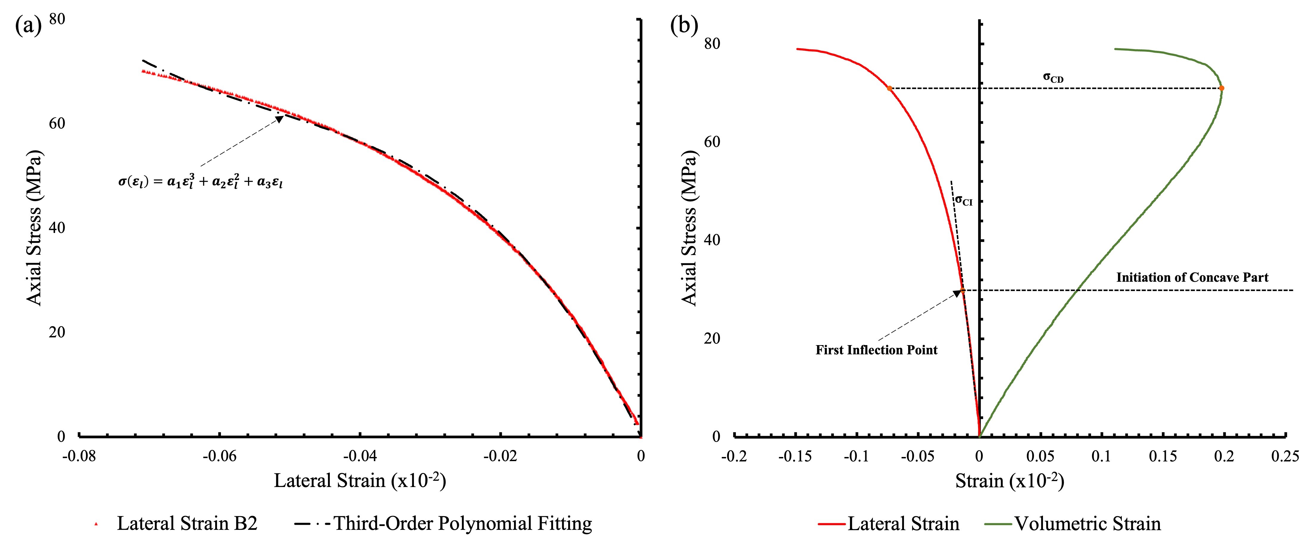
Taking the Brazilian disk as the subject of our research, we utilize a circular sample with a radius of 50 mm and a density of 2600 kg/m³. The dimensions of the sample model mirror those of the macroscopic model, allowing for seamless comparisons. Comprising 38,045 particles, the sample model exhibits a porosity of 0.11, with particle radius ranging from 0.2 mm to 0.28 mm, adhering to a Gaussian distribution. Employing a linear parallel bond model, the sample is constructed and calibrated using indoor experimental results, specifically selecting a single fracture dip angle of 0° for calibration purposes. The stiffness of the sample can be modulated by adjusting the size of emod, while pb_ten and pb_com influence the strength, and pb_fa alters the slope of the stress-strain curve envelope. Drawing upon the elastic modulus, uniaxial compressive strength, and splitting tensile strength of marble, we adopt the "trial and error method" to iteratively refine the microscopic parameters until the macroscopic mechanical properties of the model align with our specified requirements. Ultimately, the microscopic parameters are determined.
The calibration outcomes are presented in , where it is evident that the stress-strain curve's progression pattern and ultimate configuration of the sample with a 0° angle, both in the indoor experimental setup and the corresponding numerical simulation, exhibit striking similarities. This similarity forms a crucial foundation for parameter calibration.
Based on macroscopic parameters, calibration is conducted, concluding when the numerical simulation's displacement-load curve aligns precisely with the indoor experimental outcomes. The calibrated parameters are detailed in .
3. Numerical Simulation Results
3.1. Model Loading Method
The previously simulated model's side walls have been eliminated to replicate the scenario of negligible or minimal surrounding pressure in the experiment, preserving only two horizontal walls as loading plates. Subsequently, a uniaxial compression test is performed on the modified model. A precise load is applied to the upper and lower walls, prompting them to move in opposite directions at a constant rate of 5 mm/min. Upon reaching a stress level exceeding 70% of the peak stress, the loading process is halted, and a detailed stress-strain curve depicting the model's behavior during uniaxial compression is generated.
3.2. Displacement field analysis
shows the image of the displacement field in the destruction form of the sample with different fractures after loading. As can be seen from the upper figure, the different inclination angles have a significant impact on the displacement field. When the inclination is 0°, the displacement in the horizontal direction is divided into two halves along the loading direction. The displacement at the right end is greater than that at the left end; the vertical displacement is less than the horizontal displacement, and the lower displacement is greater than the upper displacement, resulting in an overall split failure. As the angle increases, crack development forms into wing-shaped cracks, the displacement field is still separated by the main crack, but both ends and the crack angle also increase. The number of cracks shows a trend of initial increase followed by a decrease, and the stress-strain curve exhibits a similar trend. The change in inclination does not result in a linear development of the number of cracks and peak stress. When the inclination reaches the maximum of 90°, the displacement field is divided into nearly equal halves. Cracks are formed along both ends of the main crack, and the number of cracks reaches its maximum. From the stress-strain curve, the stiffness of the sample reaches its maximum, making it easier for cracks to develop in the sample with greater stiffness.
3.3. Stress-strain relationship
The stress-strain plots drawn in numerical simulations of PFC usually represent the macroscopic mechanical response of a rock or soil during loading. The stress on this graph usually refers to the principal stress, which means that at a point inside the material, according to the Mohr stress circle theory, it can be decomposed into a combination of positive stress (or tensile stress) and shear stress. In rock mechanics, the principal stress is typically used to describe the mechanical behavior of the rock under uniaxial compression or triaxial compression conditions. Therefore, the stress-strain graph in the PFC simulation can reflect the changes in principal stress of the material during loading.
The PFC numerical simulation of the uniaxial compression stress-strain curve under different fracture inclination angles and uniaxial compression stress-strain curves under different fracture horizontal projection distances are shown in . As observed in the loading curve of each sample, the shape of the prefabricated crack significantly affects the results. The initial compaction process of the crack sample is longer than that of the complete sample; the linear elastic growth phase of the complete sample is longer, and its overall loading curve is relatively smooth. However, the linear elastic phase of the crack samples is relatively short, with significant stress drop points and fluctuation characteristics on the loading curve. This results from the extension of the internal cracks. After the curve undergoes a long evolution, it presents certain softening and residual properties, indicating that the rock still has a certain bearing capacity after rupture.
Based on the numerical simulation presented in (a), the inclination of cracks exerts a profound influence on the stress-strain curve during the rock mass failure process. The investigation reveals that both the peak stress and the elastic modulus of the rock mass initially decline and subsequently increase. In detail, the average peak stress diminishes as the crack inclination angle escalates from 0° to 45°, whereas it surges from 45° to 90°. This observation signifies that the peak stress of the rock mass attains its nadir at a 45° inclination, aligning with the theory that cracks propagate most extensively at this angle. Regarding energy dynamics, variations in fracture inclination modulate the energy absorption capabilities of the rock mass. Under moderate fracture inclinations, the energy absorbed by the rock mass achieves its maximum, whereas further increases in inclination lead to a decline in energy absorption. Moreover, alterations in fracture inclination can significantly influence the failure mechanism of the rock mass, with a 45° inclination exhibiting heightened sensitivity.
According to the numerical simulation in (b), the different horizontal projection distances of the two prefabricated cracks significantly affect the stress-strain curve of the rock mass. As the horizontal projection distance of the crack increases, it has a significant effect on the peak strength of the rock mass; from -10 mm to 30 mm, the peak strength increases step by step. As the negative impact of the crack on the overall stiffness of the rock mass decreases, the elastic modulus of rock mass generally increases. The smaller horizontal projection spacing of the crack lead to a lower peak strength of the rock mass because the crack provides a potential failure surface. When the horizontal projection distance is -10 mm, the rock is more prone to brittle failure. As the horizontal projection distance increases, the rock mass may exhibit more plastic deformation, with the destruction mode changing from brittle failure to plastic failure.
The above presents the sample displacement field image of different horizontal distances. When the horizontal distance of the central projection of the two cracks is 0, the horizontal displacement field is not completely separated; the two cracks produce wing-shaped cracks, but the internal cracks do not form connectivity. The displacement field formed by the two cracks exhibits variation in other areas, with particle displacement occurring at both ends. The vertical displacement field morphology is similar, but the particle displacement in the vertical direction is smaller than that in the horizontal direction. With the change in horizontal distance, at a distance of -10 mm, the displacement field is divided into three parts, with the central area displacement field being independent of the other sides. The particle displacement increases significantly, stiffness decreases, and peak stress decreases, The angle of inclination of the rock bridge complicates and destabilizes the force distributed in the central area, leading to unique and intricate patterns of destruction. As the horizontal distance advances in the positive direction, the particle displacement at the center of the circle gradually aligns with that of the two flanking sides, thereby stabilizing the force scenario. The internal cracks no longer connect, and the number of cracks begins to increase. When the distance reaches 30 mm, the upper crack expands in the direction of loading, dividing the displacement field into two parts again. The wing pattern of the lower crack develops slowly, the displacement field distribution is irregular, but the overall stiffness increases, and the number of cracks reaches its maximum.
Due to the similarity in variation curves observed across various samples during the uniaxial compression test, the crack propagation patterns exhibit distinct behaviors under differing strain levels. Specifically, upon reaching a strain of 0.057%, the initial crack formation commences, implying that with escalating strain, the sample undergoes substantial deformation, facilitating the emergence of microcracks. Notably, the majority of cracks propagate along the crack boundaries, potentially attributed to the heightened propensity for deformation and damage at these interfaces compared to the sample's interior. As the strain increases to 0.088%, the cumulative crack count initiates an upward trend, meanwhile no cracks manifesting within the sample's core, suggesting internal stability or the existence of a threshold for strain levels that are sufficient to precipitate cracking. The steady rise in total crack count underscores the continuous progression of microcrack propagation as strain gradually intensifies. Upon reaching the peak stress point, the total crack count experiences a more pronounced surge. At the extremities of the preexisting crack, the expansion of cracks and augmented axial stress contribute to crack intersections, ultimately resulting in penetration at both ends of the crack. After reaching the peak stress, despite the commencement of stress reduction, the total crack count persists in its rapid escalation. In summary, the graphical representation of crack evolution of stress and strain adheres to a characteristic pattern: initial emergence, followed by gradual increase, and culminating in rapid proliferation.
3.4. Crack extension analysis
In order to analyze the influence of crack extension, the Fish keywords for stress-strain and crack strain statistics were utilized to depict the evolution of crack numbers. Analysis of reveals that, with increasing axial loading stress, the crack number curve portrays a developmental trend distinctly marked by an initial slow onset, which subsequently undergoes swift growth. This curve can be roughly divided into three stages: approximately 70% of the peak stress corresponds to the crack initiation stage, followed by a slow growth phase near the peak stress, and finally an accelerated expansion phase post-peak stress.
Different dips significantly influence the pattern of crack extension, as shown in , and , for single fractures with varying inclination, when the dip is 0°, the middle stress concentration of the crack causes the crack to respond to vertical loading and deformation, leading to extension from the center of the crack rather than from both ends. This results in the crack propagating to the ends of the sample and ultimately presenting through the sample. When the inclination increases to 30°, both normal and shear stresses act on the surface of the fracture, leading to the formation of wing-shaped cracks that extend from the tips toward the loading direction at a certain angle. As the angle increases, the number of cracks decreases, likely due to a reduction in stiffness, as indicated by the stress-strain curve. When the inclination reaches 60°, stiffness begins to increase, and the number of cracks also starts to rise, with the direction of microcrack distribution becoming more consistent. At 90°, the crack angle aligns with the loading angle, and the test sample experiences extension from both ends of the crack, demonstrating overall brittle fracture characteristics.
The distinct failure modes arising from prefabricated cracks, which are either perpendicular or inclined to the loading direction, vary significantly. Specifically, at a 0° inclination, the crack propagation commences from the center of the prefabricated crack. Conversely, as the inclination angle increases, wing-shaped cracks emerge, resulting in diverse failure modes due to the shifting positions of stress concentration.
For samples with varying horizontal distances between the two cracks, when the horizontal distance is 0 mm, wing-shaped cracks form at both ends of the cracks. Due to the initial angle of the cracks, these wing-shaped cracks arise directly from the complex interaction of the stresses, correlating with the effects of different inclination angles observed in the previous experiments. Notably, the medial wing-shaped cracks do not penetrate, and secondary cracks primarily form at the upper and lower ends of the sample. At a distance of -10 mm, the inclination angle of the rock bridge increases, creating a complex force area at the center of the medial crack. This chaotic direction of particle displacement reduces overall stability, leading to a decrease in peak stress. When the distance is 10 mm, the inclination angle of the rock bridge decreases, allowing the medial wing-shaped cracks to develop, with particles in the central area being displaced from all directions, resulting in greater stability. Secondary cracks form at the tips of the main crack, and the number of cracks begins to increase. As the horizontal distance continues to increase, the angle between the wing-shaped cracks and the prefabricated cracks also increases, enhancing stability in the central part. Secondary cracks form at the junctions between the loading ends and the wing-shaped cracks, further increasing the number of cracks. When the distance reaches 30 mm, the upper wing crack penetrates the sample, while the lower lateral crack's extension length decreases, concentrating stress and limiting crack development at both ends. Damage is thus localized at the top, resulting in increased overall strength and a higher number of cracks.
5. Conclusions
In this paper, we utilize the particle flow software PFC to conduct a uniaxial compression simulation test on rock, providing a detailed analysis of the inclination and horizontal projection distance of microscopic mechanical parameters, destruction characteristics, and the influence on crack development processes. This research reveals the destruction mechanism of rock under uniaxial compression. The main conclusions are as follows:
This article systematically studies the number and extension patterns of cracks. Through PFC numerical simulation, we analyze the effects of different crack inclinations and horizontal projection distances on crack numbers and extensions. This systematic study provides a new perspective on understanding the crack extension mechanisms.
The stress-strain behavior of the red sandstone Brazilian disc sample demonstrates brittle fracture characteristics. The peak stress of the sample increases with crack inclination, reaching a minimum at θ = 45°. As the horizontal projection distance of cracks increases, it impacts the peak strength of the rock mass. From -10 mm to 30 mm, the peak strength increases step by step. When the horizontal projection distance is -10 mm, the rock mass is more prone to brittle destruction. As the horizontal projection distance increases, the rock mass may exhibit more plastic deformation, and the destruction mode may shift from brittle to plastic failure.
With the increase of axial loading stress, the crack number curve exhibits an overall trend of "initial slow acceleration," which can be roughly divided into three stages: the crack initiation stage before about 50% of the peak stress, the slow growth stage near the peak stress, and the accelerated expansion stage after the peak stress. When the dip angle of the precast crack is 0°, the crack starts from the middle and extends along the loading direction. At dip angles of 30° to 60°, typical "wing crack" characteristics are observed. When the crack dip reaches 90°, the crack extends along the direction of the precast crack.
The significance of the PFC simulation experiment lies in its emphasis on the importance of simulating the fracture and destruction processes of rock masses. This study points out that PFC simulations can observe the destruction processes of rock materials from a microscopic perspective, providing a reference for understanding the mechanical mechanisms of crack formation in rock masses. The research presented in this article has guiding significance for practical engineering and pre-engineering inspections. The shape and distribution of cracks can significantly impact foundational stability. Therefore, continuous monitoring of cracks is crucial in engineering to prevent further damage and destruction.